
Update 7/2/14 First of all, thanks Z for pointing out the two schematics that are now considered dangerous, in the sense that they could lead to an initial ‘zap’ and possible burn.
As I’ve mentioned earlier, I myself am not an electronics person. The notion of ‘Open tDCS’ was to develop an excellent device through Upverter (or similar online platform), that anyone could then order directly from a Chinese manufacturer (thereby circumnavigating any regulation issues etc).
We have yet to find an engineer to lead and build the design team and my thoughts about why are simply that people are too busy, or that they see a possible financial gain for their own device somewhere down the road. Considering the original post/Upverter account is a year and a half old, it seems unlikely we’ll find someone, but you never know!
——————————
Upverter is an online platform that allows for electronics to be designed, parted, and built. As I understand it, once the design is fixed, you shop for parts – inside of Upverter, and then submit your project (to Upverter’s Chinese partners) to be built. I’d mentioned Upverter on the tDCS subReddit a few times. I was hoping to pique the curiosity of the engineer types that had designed and built their own tDCS devices… Crowdsource the design, and then anyone can order one!
What happened was I got an email from Eric Evenchick, a ‘customer success / hardware engineer person’ at Upverter! Eric had seen my post and written to help. He waived the team fee, set up the project and ported the OpenStim Arduino-based tDCS design, by ohsnapitsnathan (Reddit handle).
I hope I didn’t step on any toes by collecting these schematics to one place. I wanted engineers to be able to see quickly how other designers have thought about building their devices. If you’re an engineer type interested in tDCS please join our Upverter team.
It feels silly to put it this way, when the very nature of Open implies extreme democracy, but here goes… Here’s my vision of an Open tDCS project.
- Build an Upverter team
- Design, part, and prototype a minimum viable tDCS device
- Working with an online ‘cognitive test’ site, build a protocol for measuring the effectiveness of tDCS
Later on we could develop a multi-channel device, and maybe this is just a fantasy, but if it could interact with the internet, researchers could design tests and collect data non-locally. How cool would that be?
The rest of this post will attempt to collect in one place the various schematics I’ve seen for DIY tDCS devices.
I called this one Imgur earlier on the blog. It comes from 55tfg7879fe42e345 (Reddit handle)

tDCS by 55tfg7879fe42e345
brmlab our Czech friends

The Focus device.
Focus V 1
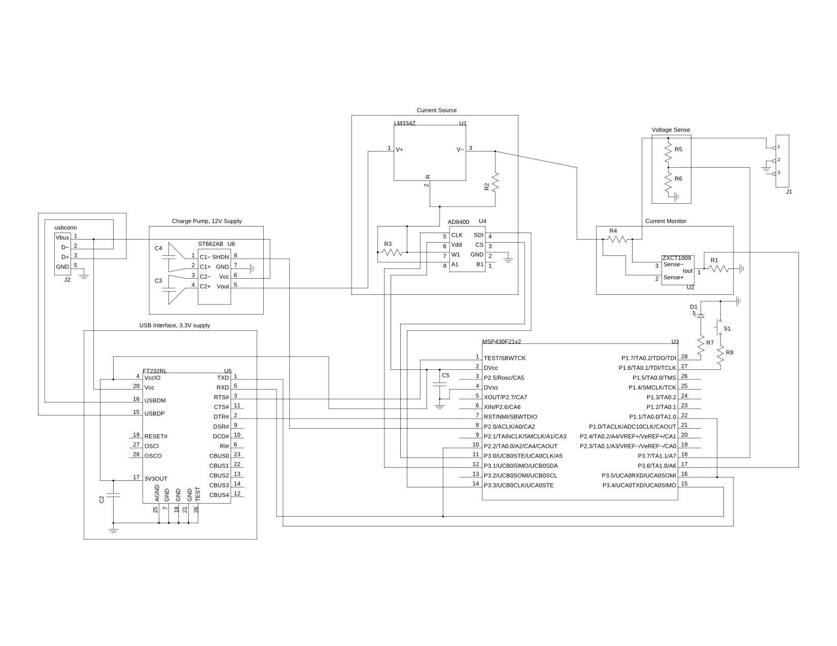
And then the more advanced, programmable tDCS devices. OpenStim

OpenStim
Open Stim Multi-Channel
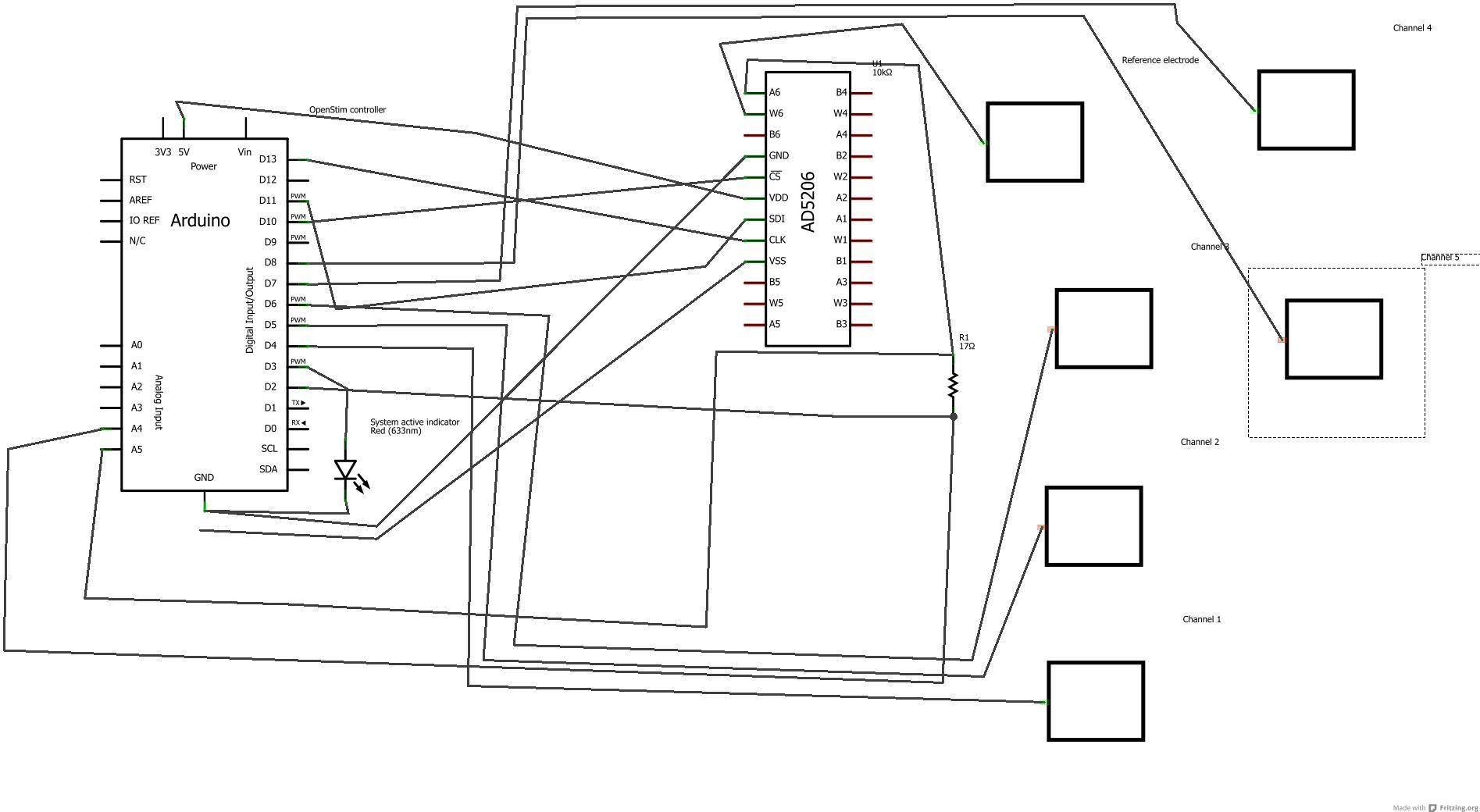
OpenStim Multi-Channel
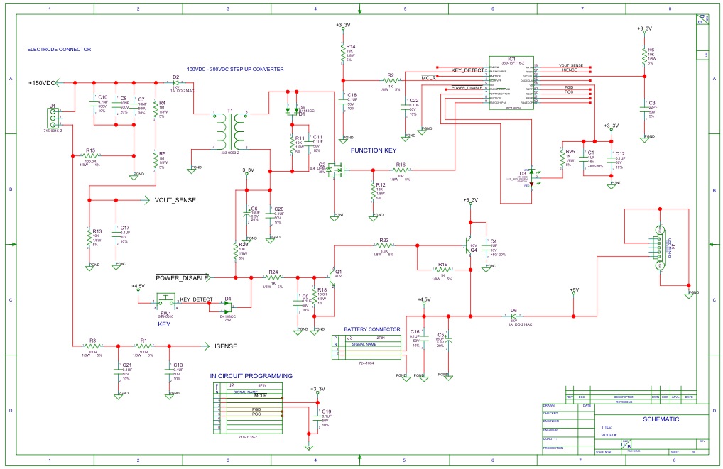
Shawn Nock Version 2
Shawn Nock Version 2
If you know of a schematic I missed please let me know, and even if you’re not an engineer, consider joining Upverter and ‘Following’ our project.
I would like to add the circuit of the PriorMind System device here as well.
http://priormind.com/img/circuit.jpg
Explain:
18V is used because 9V is insufficient to reach 2mA for most of the montages placing electrode on shoulder.
Capacitor is add for a smooth start.
Low resistance, precise pot is used to enable a linear adjustment of intensity.
Typical LM334 design, and with an additional CRD for current limiting.
Should you have any question about the circuit, please feel free to email me at info@priormind.com
Or you can come to our website http://www.priormind.com for more information
The PDF link for the Focus device seems to be broken.
Is there a PDF available?
Yeah, it looks like they removed it (so I removed the link). At least we have the jpg. Same info. Best, John
Thanks John,
True, I can see what the components are – I just can’t read the component values. Was there a higher resolution drawing and/or a parts list around?
have a good one,
Terry
When you click on the image it opens the largest res jpg I have. Surprisingly a search for “focus-v1-schematic.pdf”, which was the file name of the pdf results in nothing, nor Archive.org. Probably someone on the Reddit tdcs board has one.
You should really take off those or put a BIG warning. The schematas in question are:
The first – “Go Flow DCS”
The third – “Shawn Nock tdcs V1”
If you turn on the device before you attach it (for battery test or if you need to readjust), it will load the capacitor and zap you with full power of the capacitor (higher than the battery), once you attach the electrodes.
Thanks Z! Done. I’ve been asking for a long time for someone to point out exactly the offending schematics. Much appreciated!
P.S.: http://www.darwinawards.com/darwin/darwin1999-50.html
I am NOT “Barry” who warned you that it’s dangerous to use a
” device using a LM334z has a 470uF capacitor across the electrodes.”
But looking at the pictures above, I can see _at_least_ two of the diagrams show a capacitor across the electrodes.
The first image specifies 470 uF; further down the page a different image just identifies “C1” — which is also a capacitor, and also placed across (between) the electrode wires.
So at least two of the circuits have the hazard he warns you about.
Others may also.
“Be careful about reading health books. You may die of a misprint.” — Mark Twain
Barry Klein on May 2, 2014 at 10:22 am said:
Your comment is awaiting moderation.
Your schematic of a device using a LM334z has a 470uF capacitor across the electrodes. This is BAD.
What you have there is a constant current source feeding into a capacitor. Loading of the capacitor (your head) – when you connect to your head – has no current limiting at all – just your head. Exactly defeating what the LM334z is supposed to do. Change the schematic or take it off your site.
Barry can you Right Click and copy the url of the offending schematic and past it in here so I know exactly which you’re talking about. I don’t speak electronics myself. I do like to collect the various schematics that pop up. Thanks!
…so this is where it came from. Drop the capacitor!
You NEVER put a capacitor across a current regulated loop! Never! It’s dangerous, especially a 450uF one…
That’s what happens when you get people trying to design circuits who are not circuit designers. There’s a bit more to good circuit design than meets the eye. It might look simple but it isn’t. You’d think think people would no better than to cobble togethor circuits with limited knowledge and experience (despite how qualified they think they are) and then proceed to connect it to their brain no less. Of course, if they’re that misguided, maybe a good jolt to the head might not do that much harm! Can’t harm what isn’t there to begin with.
Ya, I actually tested that circuit on my arm. Got a burst of coronal shock from what I assumed was the capacitance.
The problem comes into play if the current source is switched on and the circuit breaks between anode and cathode sponges. If you reconnect the sponges while the current source is still running, the sponges will shock you pretty good. Even with the 5mA fast-blow fuse.