
Read the full article here.
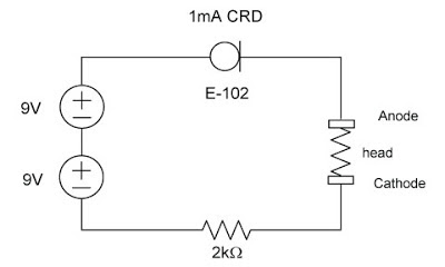
Above is a schematic for a simple tDCS circuit that will supply 1mA. The CRD (E-102) maintains a 1mA regulated current to the head (between the Anode and Cathode). The E-102 can be purchased at www.mouser.com. Two 9V batteries are better than one, particularly if you have a less than perfect electrode-head interface, and it will last much longer without the need to change the battery; also the CRD has a 1V-2V drop so the full battery voltage is not present at the Anode. In using the CRD, you have a two pin regulator instead of a three pin regulator and a resistor for the LM334, which means simpler construction.
via Insight, a growth project driven by tDCS: Simple DIY TDCS circuit using CRDs.
A quick look into TRNS shows it most definitely is created from a computer generated random noise generator controlled to specific current and voltage amplitudes and approx 100Hz to 640Hz.
And for TACS, one paper I saw had 6Hz, 10Hz, and 25Hz with sham. These signals would most likely be created using a variable oscillator, then magnifying and carefully controlling current amplitude before output to electrodes. A DC to AC inverter is more commonly used for power applications with higher levels of current output; I don’t think this is a good way to create the sinusoidal signal of TACS.
Huh. Thanks. I’m not sure how the openstim does it then, being all on one arduino. I didn’t think one could do *all* of the inverting plus oscillating *and* randomizing at the same time on one of them. Those things must kick but. (Or a lot must be offloaded to the PC it would be connected to?)
Those schematics I saw for chip based CES were for oscillators, I was just hoping to try making a simplified (discrete parts) proof of concept with the switching inverter, even if it’s not really usable- I hate relying on things I don’t have the simplest understanding of…seems like asking for trouble.
You can add a 1mH inductor in series and a 10uF (25V) cap in parallel (making an LC filter) to dampen any transients. It is not long enough to prevent the flash but it slows turn on to about 500ms, definitely enough to dampen any transients. And a 1mH thru hole inductor can be found smaller than 1cm in diameter from Digikey.
Hello. I’m not very knowledgeable about electronics but I see that LC circuits seem to oscillate polarities through it. Does this result in an AC current at the electrodes?
Thanks.
To create an oscillator from an LC circuit you need to amplify the resonant component (simply done with a transistor). In this passive configuration it acts as a low pass filter, filtering out the higher frequencies and letting through the lower frequency, including DC. Ideally you would set the 3dB point around 60Hz, but then you would have to have a huge inductor and huge capacitor. The 1mH and 10uF choice will dampen fast transients (in the ns range) that may occur in the basic CRD circuit.
So if it was not clear, no there is definitely no AC signal at the output (only smooth DC after turn on) and the LC low pass filter, removes any fast transients at turn on.
He he. Yeah, you lost me with the 3 decibel point but I got the message that it doesn’t output AC and that while possible, it wouldn’t be all that practical.
So I gather that AC output would be way easier by switching alone. But I’m such a novice I can’t quite get my head around it, as in I may be confusing the way transistors work with relays (i.e. a power in, a power out and a control wire…)
PS> Thanks, and while I’m interested in doing tACS that’s just an afterthought.
Not to drift too far off topic here- while I already have a schematic for a chip based tACS (“CES”, but it’s tACS) I really want to be able to make a simplified AC source even if it is fixed at a given frequency. I know the OpenStim can put out AC, apparently inverted DC via switching but again, I can’t seem to wrap my head around it. Not even the idealized circuit.
Thanks again.
Not sure about your TACS setup but considering the difference between DC, AC and random signal, think what the signal would look like if you see it on an oscilloscope. A DC signal would be flat at a particular level, say 15V, and stay there. An AC signal (at one frequency) would often look like a sinusoid, swinging positive and negative (to a positive and negative amplitude) and the frequency would be how many times it swings in one second, say 2kHz is 2000 times a second. A random signal will go within a certain amplitude, say -5V to +5V, and swing back and forth at varied frequencies, say 600Hz to 2kHz.
The signals of TDCS, TACS, and TRNS are something like this but at the particular frequencies and amplitudes determined by the research.
Yes I know as much though it seems that the
“random” in tRNS might or *may* only refer to the fact that it doesn’t consist of only one frequency all of the time; in comparison live experimental jazz is pretty *random* in the literal sense while a more traditional piece isn’t “random” at all…which doesn’t mean it couldn’t be off some random number generator but I’ve believe that the OpenStim uses a preset, basically a recording of the “notes” and timings, as opposed to “randomness.”
Whew, sorry for the length of that!
There was a post on the tdcs subbreddit with a few DIY CES schematics. Not much more involved than an LM 317 or 334 based tDCS rig.
The thing is I can *picture* the basic method that an LM317 or even a CRD does it’s thing while I’m not too clear on the physical reality of a transistor inverter, if you see what I mean.
I mean I can think of it like the way the trains on a model railroad could be re-routed and left traveling in the opposite direction afterward but this neglects the actual details of the way transistors are wired, I think.
As I said I’m a complete novice electronically.
While I’m generally content with tDCS, I do intend to investigate tACS and eventually tRNS as well…I just want a much firmer grounding in the basics first. Like being able to build a simpler 1-2mA DC to AC inverter with all discrete elements.
Okay so the way a constant current diode works is by being a variable resistor, based on the current flowing through it. If there is no current flowing through, it acts as a short circuit. (Well ALMOST a short circuit, but we don’t care about that for now.)
Now if you have 18V of input voltage, 2mA of current means the combined resistance of the circuit is 9kOhm. The way you can easily imagine what the diode does is, based on all the resistance in series with it, it becomes the missing piece to get the necessary 9kOhm.
Now the interesting part is where the series resistance is greater than 9kOhm. In this case, the diode will decide it’s no longer needed, and become a short circuit. Now if that series resistance is near infinite, then there is no current, and when there is no current, there is no voltage drop. Not only through the diodes, but neither through anything else.
During the turn-on transients, there will be a nanosecond when you actually have that 18 Volts between the terminals, even though significant current cannot flow, the voltage will cause arcing, and will trip some neurons’ action potential.
As putting a pot in series, just think what will happen. The response will be abysmally non-linear. Try plotting it. 🙂 In reality it will very much be like just flicking a switch on or off at one end, and the rest of the pot travel will not have any effect.
Anyway, the idea itself is pretty cool, but without further comfort-improving devices like a shunt pot, I’d say a simple 9V battery+resistor+pot+ammeter design is preferrable.
The best facet of using diodes is that they are pretty robust and very little can go wrong with them, setting a safe maximum on the possible current. The fact however that the maximum voltage is no longer 9V but 18V, and that you are regulating current, not voltage, makes it potentially un-fun to use. XD
Well my first idea was a 50kOhm pot parallel with the load, with the wiper connected to ground. The only problem with this is that it’s vastly nonlinear…
So the solution I settled on is to use a 50kOhm audio taper pot in the above configuration. It’s not quite linear, but good enough.
(Take an audio pot which has a graph of the taper, and plot the current values for every 10% of its rotation using the current divider rule, you’ll see what I mean.)
Now this means I’ll be wasting 10% of the current, but since my diodes have a positive error around 10%, I’m not that concerned.
OK, I think I see. Thank you. As it happens I never put a variable resistor in my three-pin regulator so that hard a transition (0-2.3mA) doesn’t seem bother me as much as it might others. Still a lot less of a jolt than in this case…so I’ll try it your way!
Just to see if I understand; I assume you mean that you’re estimating the combined resistance of your electrodes and yourself to be about 5kOhm and that the 50kOhm (max) in parallel with you, given the current divider rule, means 90% goes your way with 10% wasted through the pot during your session?
So then…IF I have that right, it means that -if- you were worried about that last 10% you could just put a switch, or a pot with a built-in switch, in that parallel connection and simply open the circuit while ‘under-way’? Cool.
Thank you.
Yea… 🙂
Another thing I want to experiment with is adding an inductive choke. As I pointed out on another article, putting a “soft start capacitor” totally defeats the purpose of having a current regulator in the first place. However, a choke will try to hold current, to the detriment of voltage stability (which is what we want).
I don’t have a scope at hand right now, but once I get near one, I’ll do some transient checks on both voltage and current and see if a choke helps (I’m pretty sure it will).
The only problem is that given the R values in the circuit, I don’t think anything less than a 10H choke would amount to much, and those are heavy and huge (like 3 inches across).
Anyway, that’s just a further level of protection, the pot by itself should be enough for safety.
Still. XD It wasn’t very pleasant when I disconnected my test setup, and as a quick goodbye I got a flash of light across my entire field of vision, and a rather unsavory jolt.
Now that light means a bunch of neurons got their action potentials reached – which is done by voltage, hence I’m pretty certain there was a voltage spike involved. (Also, it’s something one should avoid if possible, it’s not TDCS but electric shock therapy from there on out.)
Great…and yeah, if your ‘trodes weren’t near your eyebrows and you still saw a big flash that’s gonna sting if not burn.
I seriously need to bust out my breadboard and just mess around, but I’ll as you this- can’t you throttle the CRD with a pot upstream from it?
I had the impression it just sets an upper limit on current without actively trading voltage for higher current, was I wrong? If so, wouldn’t there still be a point where the voltage is too low for it to keep the amps up? Maybe it’d be too abrupt to soften the transition.
Also if I was wrong about that wouldn’t a plain voltage regulator with a variable r-set still do the trick? Not quite as simple then I guess.
…also, it would seem that these diodes are manufactured to a tolerance of 20% in regulated current (or my batch is defective), so don’t expect spot-on accuracy.
This design suffers from several fatal flaws. I guess it’s good enough, but in certain areas it’s worse than a single battery + resistor setup.
Due to the system being essentially a current source, the switch on and switch off transients are TERRIBLE. What happens is, as the switch transients disrupt current flow, the diodes open wide, and let 18VDC right onto the ‘trodes, resulting in arcing, and potentially a ~9mA current spike.
I tried it, it feels really bad.
I’m currently working on a way to eliminate this problem, essentially a controlled crowbar (current divider) between the anode and the common ground.
Hello. I’ve made some simple regulated TDCS circuits but I am still largely an electronics novice. By “controlled crowbar” do you mean something like a load across the leads in parallel with my head, with a pot between these parallel loads? Maybe a ~3Kohm resistor in parallel and a large 1Mohm pot to shift the entire start-up transient to the dummy load?
Thanks.
Sort-of. A “crowbar” shunts (shorts) excess voltage/current automatically. See Wikipedia’s definition of Crowbar (Circuit.)