Insight, a growth project driven by tDCS: Cognitive enhancement montage location: L A DLPFC, R C Supra orbital

Even though measuring from cranial landmarks is one way to find these points, I always question measuring on the head, or body, because of the size differences between people. Hence to make it easier to locate the points, below are numerous pictures.

Left Anode Dorsolateral Prefrontal Cortex (DLPFC)
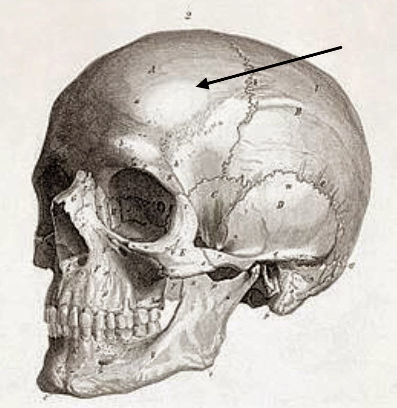
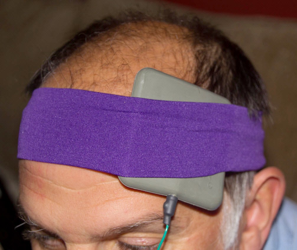
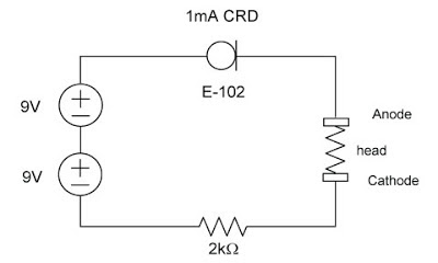
The left is obviously the left side of the head, and the anode is the more positive of the two leads (green wire on the Cognitive kit); current goes from electronics to anode through the head to cathode back to the electronics. For the position of the DLPFC, check out the cranium below:

And on me pointing and with a sponge electrode(see there is an advantage to having little hair, better tDCS montage location and better electrode connection).

via Insight, a growth project driven by tDCS: Cognitive enhancement montage location: L A DLPFC, R C Supra orbital.

A little less Simple DIY TDCS circuit using CRDs | Insight

Regarding the transients at turn on, that is a circuit issue. So to remedy, it is easy to add an LC filter at the output see picture below for new schematic. The LC filter acts to dampen any transients. Bench testing shows the ramp up to be 500ms, which is plenty to dampen any turn on pulses, but unfortunately not enough to prevent any flash that occurs with certain montages. At mouser.com, the L can be 22R105C and the C can be UKL1E100KDDANA.

via Insight, a growth project driven by tDCS: A little less Simple DIY TDCS circuit using CRDs.

Insight, a growth project driven by tDCS: Simple DIY TDCS circuit using CRDs

 Read the full article here.

Above is a schematic for a simple tDCS circuit that will supply 1mA. The CRD (E-102) maintains a 1mA regulated current to the head (between the Anode and Cathode). The E-102 can be purchased at www.mouser.com. Two 9V batteries are better than one, particularly if you have a less than perfect electrode-head interface, and it will last much longer without the need to change the battery; also the CRD has a 1V-2V drop so the full battery voltage is not present at the Anode. In using the CRD, you have a two pin regulator instead of a three pin regulator and a resistor for the LM334, which means simpler construction.

via Insight, a growth project driven by tDCS: Simple DIY TDCS circuit using CRDs.