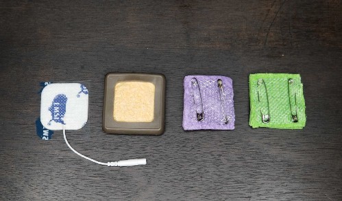
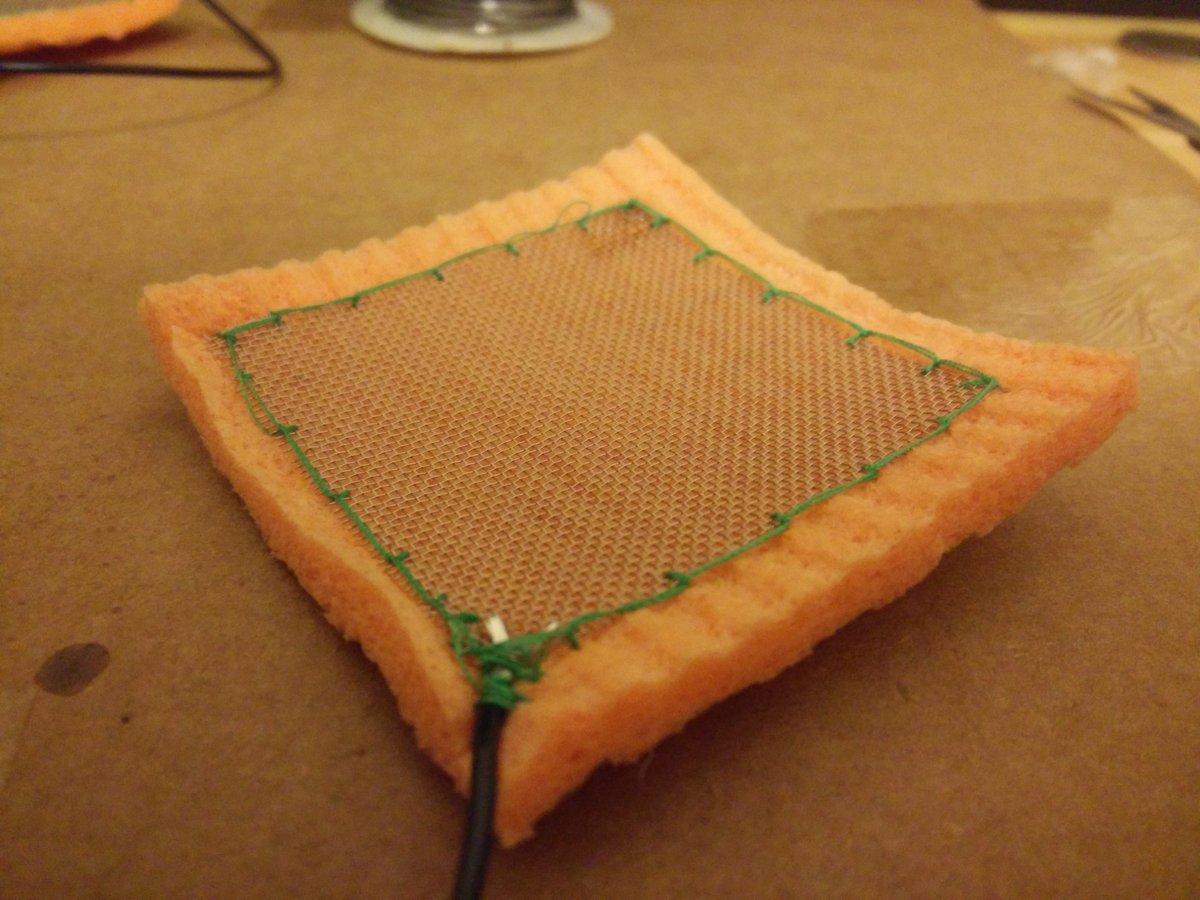
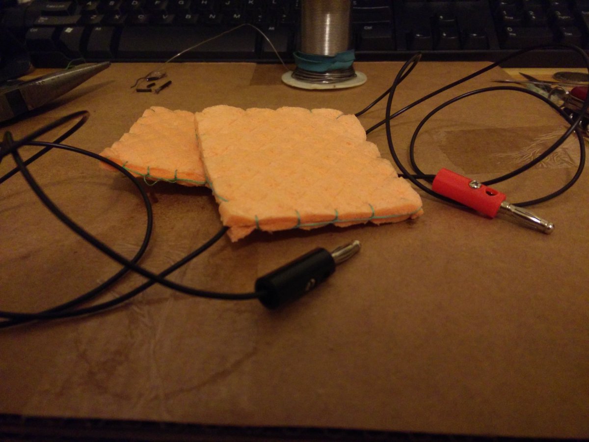
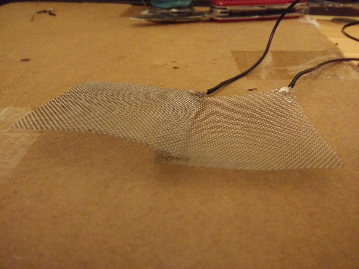
DIY Electrodes | Melanie Segado

[Update 7/4/19] Just noticed this excellent DIY electrode post from Vagabond Banana who seems to be embarking on a DIY tDCS build/workshop project.
Is DIY As Good As Clinical/Commercial When It Comes To tDCS Electrodes?

Melanie Segado is a PhD Candidate in Neuroscience at McGill University | CoFounder @NeuroTechX | Cellist | Currently interested in #DIY #TDCS
via Twitter @sciencelaer

https://twitter.com/sciencelaer/status/770075458184634368

tdcsMelaniSegadoElectrodes1@sciencelaer tdcsMelaniSegadoElectrodes2@sciencelaer tdcsMelaniSegadoElectrodes3@sciencelaer

Caputron Now Carrying Foc.us V2 Device

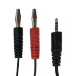
Robin at Caputron dropped me a note to let me know they are now carrying the Foc.us V2 device. Purchased alone, it does not include electrodes, but there is an option to add their ‘starter kit’ which includes the Caputron Universal Strap, Caputron Banana Adapter Cable for Focus Device, and Choice of 2×2 or 3×3 Electrodes. (Use diytdcs at checkout for generous discount). Foc.us V2 Device at Caputron.
If what attracted you to tDCS is all the news (and hype) around the possible benefits, cognitive and otherwise, that tDCS may provide, then I recommend the Foc.us V2 device. It’s had a thorough going over, and apart from the (then included) electrodes, proved to be an amazing piece of gear. tDCS, tACS, tRNS, tPCS in a single sub $300 unit with a software interface!

Elsewhere on the blog I’ve stated that I recommend the ActivaDose ll device. This is an FDA approved device – it’s NOT FDA approved for tDCS – it’s approval is for use as an Iontophoresis device. The point is that the electronics and workmanship have attained an FDA level of approval. It’s simple and straightforward to use.

The only reason I haven’t recommended other tDCS devices on the market is because I’m not in a position to analyze the quality of their workmanship myself. I recommend the Activadose ll because people looking to experiment with tDCS for the treatment of depression can’t be assumed to have a toolset for determining the mechanical workmanship of an electrical device they’re going to be attaching to their heads! The Activadose ll, an FDA approved device, at least assures the buyer the device itself is of high quality. It’s also more likely to retain some resale value in the event someone decides later on to sell it.

I recommend the Foc.us V2 because of it’s variety of stimulation modes. Folks who are sophisticated enough about neurostimulation to be experimenting with cognitive enhancement would obviously benefit from having the option to test other forms of stimulation that frequently come up in the scientific literature.

When you use code diytdcs at checkout at  Caputron you get a discount, and I get a small commission.

New Electrodes From Focus and Caputron | Speak Wisdom

Dr. Williams at SpeakWisdom takes a look at the new focus electrodes as well as new Caputron Amrex-style electrodes. Electrode Wars! (Well Not Quite)

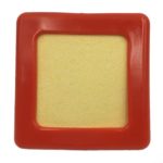
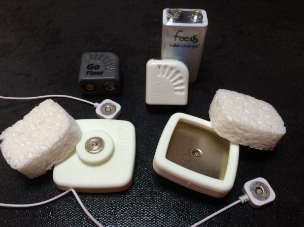
foc.us (famous for the foc.us V2 brain stimulation device and the new Go Flow tDCS device) is just releasing a new sponge electrode system  for the V2 and Go Flow that is very interesting! It consists of a rubber-like shell (about 2×2) and sponges that when inserted result in a 1.25 x 1.25 inch sponge contact area. To connect to the foc.us sponge electrodes, you need a special V2/Go Flow cable that attaches magnetically to the electrode shell. That means the problem of having an electrode jerked off of your head should you become tangled somehow goes away. This is a vastly better connection technology than the banana plug and socket used by many manufactures.

IMG_3146

A technical guide to tDCS, and related non-invasive brain stimulation tools | Clinical Neurophysiology

Many of the leading tDCS researchers contribute to this Open Access article on clinical application of transcranial electrical stimulation (tES) techniques. Read it online, or download the pdf. (HatTip to Reddit user gi67)

  1. 1. Introduction
  2. 2. Transcranial direct current stimulation
    1. 2.1. Selecting and preparing electrodes and contact medium
    2. 2.2. Selecting and preparing electrode placement
    3. 2.3. Selecting a stimulation protocol
    4. 2.4. Use of blinding and sham
    5. 2.5. Safety versus tolerability
    6. 2.6. Considerations for transcutaneous spinal DC stimulation (tsDCS)
    7. 2.7. Considerations for cerebellar tDCS
      1. 2.7.1. Targeting the whole cerebellum
      2. 2.7.2. Targeting the cerebellar hemispheres
    8. 2.8. Selecting a stimulator
  3. 3. Transcranial alternating current stimulation (tACS)
    1. 3.1. Selecting tACS electrode placement
    2. 3.2. Selecting experimental design
    3. 3.3. Selecting stimulation parameters
    4. 3.4. Transcranial random noise stimulation (tRNS)
  4. 4. Monitoring physiological effects of tES
    1. 4.1. Monitoring physiological effects of tES with TMS
      1. 4.1.1. Monitoring of tES-induced motor cortex plasticity
    2. 4.2. Monitoring physiological effects of tES with electroencephalography (EEG) and event-related potentials (ERPs)
      1. 4.2.1. Selecting an approach
      2. 4.2.2. Integrating tES and EEG electrodes
      3. 4.2.3. Recording EEG during tES
    3. 4.3. Monitoring physiological effects of tES with magnetic resonance imaging (MRI) and magnetic resonance spectroscopy (MRS)
      1. 4.3.1. Integration of tDCS with MR
      2. 4.3.2. Considerations for concurrent MR acquisition
      3. 4.3.3. Other considerations for tDCS integrated with MR
  5. 5. Monitoring functional effects of tES
    1. 5.1. Monitoring functional effects of tES in healthy subjects
    2. 5.2. Monitoring functional effects of tES in patients
  6. 6. tDCS/tACS/tRNS in animal preparations
    1. 6.1. DC-, AC-, RN-induced membrane polarization
    2. 6.2. What can we learn from in vitro experiments?
  7. 7. tDCS and models of electric current through the brain
  8. 8. tES ethics
    1. 8.1. Education and training
    2. 8.2. Settings and procedures
    3. 8.3. Patient/subject selection
    4. 8.4. Patient/subject education and informed consent
  9. 9. Concluding remarks
  10. References

Positioning Electrodes

This instructional video demonstrates the correct way to measure and place electrodes. In a clinical setting, with a medical grade tDCS device (Soterix), a subject is measured for electrode placement on the primary motor cortex. The dorsolateral prefrontal cortex region is also shown. This is the first time I’ve seen the video on Youtube (making it easy to share). Previously it could only be found here, where an associated pdf which includes illustrations is also made available.


What is tDCS? – Improving Visual Memory | Neural Engineering Group

[Note (updated 8/9/15): Alex is using a research version of the mindGear device. The device as available to the general public does not include a tDCS program.]

The folks at the Neural Engineering Group (associated with Marom Bikson’s NY City College Neural Engineering Lab) are producing a series on tDCS. Here is their first episode!

My Notes: Could you force an action potential with tDCS? (TMS does)
Visual memory improved by non-invasive brain stimulation (paywall)
Richard P. Chi, Felipe Fregni, Allan W. Snyder
Dosage: mA x time, i.e. 30 mA minutes could be 1.5mA for 20 minutes.
Memory improvement montage: Anode between T8 & FT8, Cathode between T7 & FT7

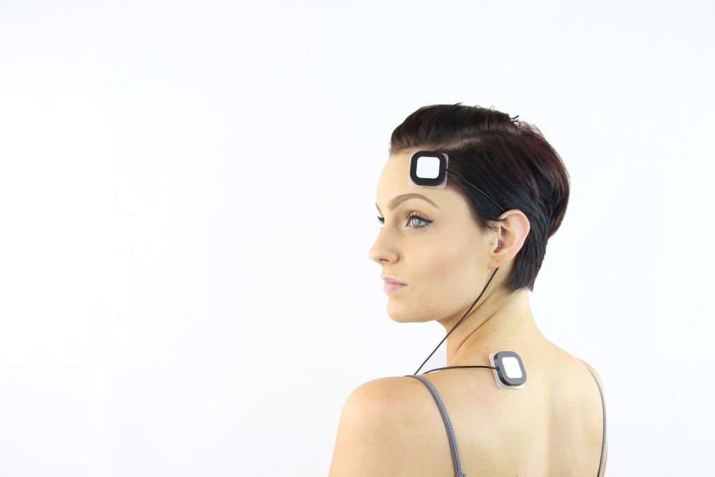
Foc.us ‘Moovs’ Electrodes

Foc.us recently released a new set of electrodes that addresses many of the issues customers and reviewers had with previous releases.

tDCSFocusAltmoovs

Also very impressed to see this on their website.

Coming soon… foc.us+
Connect and share with others like you

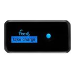
Using foc.us+ you can find experts who can help tailor the perfect program for your neuro-modulation needs. Track your progress, monitor your improvements. take charge

Foc.us is definitely listening and doing their best to stay one step ahead of everybody else.

Where Do The Electrodes Go?

Update 9/6/12: Found for the first time, a study which equates electrode placement directly with the 10/20 positioning system. The study, Modulating activity in the motor cortex affects performance for the two hands differently depending upon which hemisphere is stimulated, was published in the European Journal of Neuroscience in 2008 and is available to download as a pdf or read in Quick View.

On each day, there was one session for anodal and one for cathodal tDCS, administered while the participants sat in an office chair. On the first day, participants also underwent one session of sham tDCS. For the anodal and cathodal sessions, 1 mA tDCS was applied for 20 min. On one of the testing days, the active electrode was positioned over the participant’s left- hemisphere motor region, centered on C3 of the 10–20 international electroencephalogram system; on the other day, the active electrode was positioned over the motor region of the right hemisphere (centered on C4 of the 10–20 electroencephalogram system). The correspon- dence between C3, C4 and the primary motor cortices of the left and right hemispheres, respectively, has been confirmed by neuroimaging studies (Homan et al., 1987; Herwig et al., 2003; Okamoto et al., 2004)
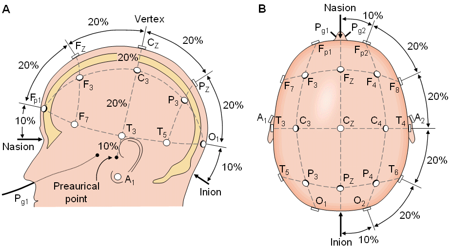
http://www.bem.fi/book/13/13.htm#03

[Source of the above image is probably http://www.bem.fi/book/13/13.htm
where it’s referred to as “Location and nomenclature of the intermediate 10% electrodes, as standardized by the American Electroencephalographic Society. (Redrawn from Sharbrough, 1991).” The author seems to also have it available on ResearchGate
https://www.researchgate.net/publication/321094865_Bioelectromagnetism_13_Electroencephalography ]

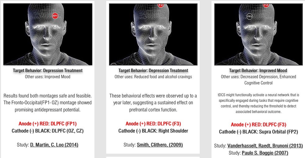
While the 10/20 positioning system (wikipedia, pdf) does seem straight-forward and easy to understand, most of the electrode sites mentioned in the publications I’m reading don’t refer to it in describing where electrodes are being placed. You’re more likely to see something like: “…after bifrontal tDCS with the anode over the right and the cathode over the left dorsolateral prefrontal cortex (DLPFC).”

But if laypeople are going to be experimenting on themselves, wouldn’t they need some sort of standard reference to enable sharing of specific electrode sites? Wouldn’t you like to be able to say something like, I placed the anode over the right dorsolateral prefronal cortex at F3 and the cathode over the left at F7? In that way it would be easy for someone else to replicate. I was looking for a diagram that would map the 10/20 system over brain regions, but didn’t find exactly what I was looking for. If you have any ideas about this please share in the comments.

In the meantime here are a couple of basic brain info sites I found. These tend toward more basic information.
Healthline Brain Map
Cold Springs Harbor 3d Brain Map